Circuit schematics and troubleshooting guides for the Electrocompaniet
amplifiers and preamplifiers, from the original 1973 Otala design through the
EC production schematics, the 1982 preamplifier, and the later NRF/Special
Version modifications.
Not ported: distortion_calculators.htm and SingleCalc.htm (an ActiveX
distortion-calculator control — only ever worked in old IE, and the control
binary itself isn’t something to carry forward) and a_strange_one.htm
(linked from the old site as “a further schematic variant”, but the actual
page content is just a generic “site under reconstruction” placeholder — no
real schematic survives there).
One gap filled in during migration: the old site’s schematics page said
“SCHEMATIC 5 is coming later” for the Special Version schematic and never
delivered it, but the scanned image (ASpecial_SpecialVersion.jpg) existed
unlinked in the old site’s files — it’s now included on the evolution of the
schematics page.
The first design was taken directly from the paper by Otala and Lohstroh, AES
1973. To it was added a power supply only. The PCB layout and the mechanical
design were done at EC.
Only 10 amplifiers were made using these schematics. None exist today.
The next series was done after early 1976, and incorporated the first changes
to the frequency compensation. The changes were made to improve the frequency
response and slew rate of the amplifier.
Referring to the schematics above, the fixes were done on the first- and
second-stage lead network (the RC’s between the emitters of the differential
pairs); the lag networks on the collector sides were removed, and the input
lag network was redimensioned.
After a breakdown of the first amplifier brought to the US, a non-intrusive
(sound-wise) protection network was added to
the amplifiers.
Several intermediate steps are missing, but at the end the design looked like
what’s shown in the next schematics, which applies for amplifiers with serial
numbers above 100 — these were heavily EC-modified. See the
History section.
Note the reduced values of all input-stage resistors, indicating the increased
quiescent current in these stages.
From serial no. 275, the Great Change was applied to the amplifiers.
This was the last of the EC designs, but in my own company I did two new
modifications: one known only as the NRF Mod., the other known as “The
Special Version”. The modifications were only further improvements, naturally
following on from the EC time. See the NRF modifications
page.
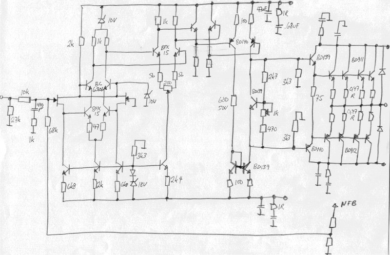
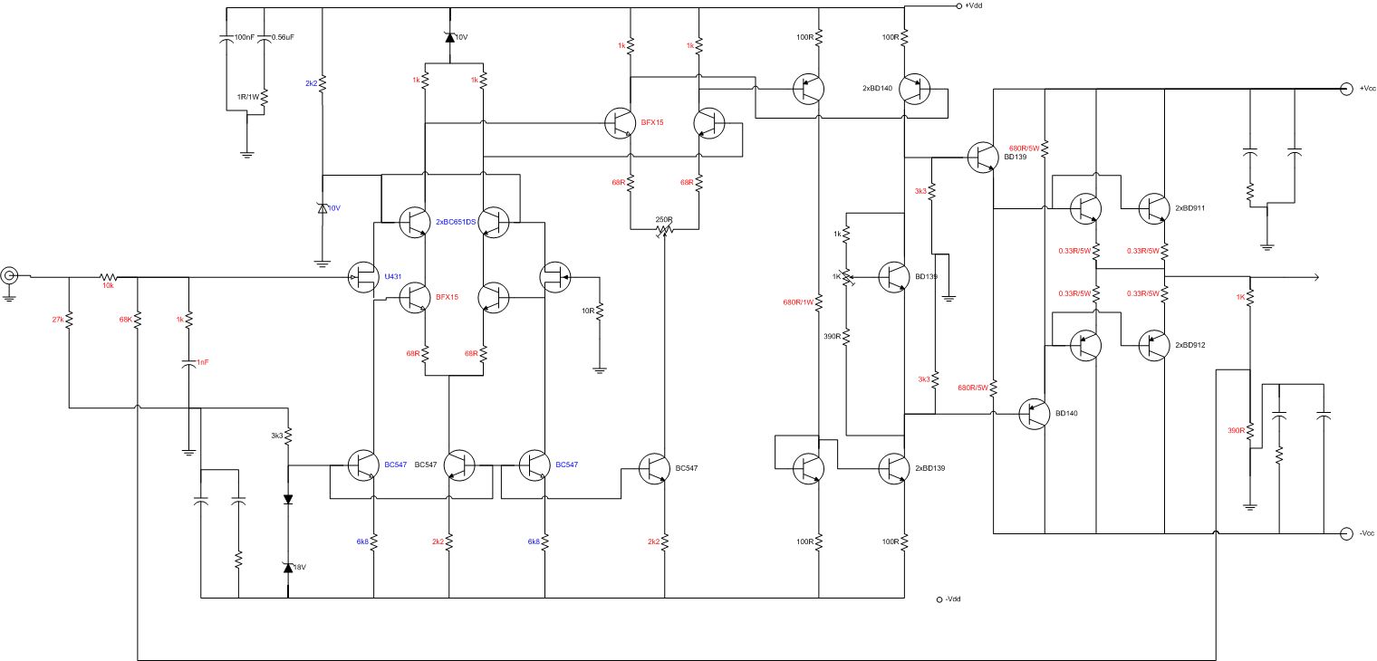
The “Special Version” schematic is shown here:
Note the heavily reduced values of the output-stage emitter resistors — down
to 0.33 ohm from 1 ohm! This reduces the AB nonlinearity, as described in my
1982 AES paper.
Note also the changed input stage, with a JFET differential pair as a source
follower. It was found that the bipolar input stage added distortion caused by
its nonlinear input base current acting on the input resistors. (Which again
shows: when we reduced the input resistors from 6k8 to 2k2, we heard a sound
improvement and believed it was caused by improved frequency-response behavior
above 20kHz — it may have been the 10dB distortion reduction that we heard!)
To reduce this distortion further, the JFET pair was added. Further, a cascode
pair was added to eliminate the Miller effect and the nonlinear voltage
modulation of the critical first stage.
The gain distribution was also changed — the 3rd stage gain was increased by
raising the load resistors from 2k2 to 3k3. More gain was needed to increase
the overall feedback to 40dB. It was found that increasing this particular
point (3rd stage) was the less critical of the options. However, we got
slightly more relative modulation effect on the 3rd stage than we wished for.
All in all, approximately 100 amplifiers were modified, and an additional 50
Special Versions were made.
By the end of the ’80s and the beginning of the ’90s, I tried a few more
changes to the amplifier design, which never made it beyond the lab bench.
Only one amp exists with these modifications. They included emitter followers
added before the 3rd stage, to reduce the modulation effect mentioned above.
Also see some of the later calculations made on this
amplifier.
What about some thoughts on the “Perfect 25W”
amplifier? Or the perfect preamplifier,
which was realized, but …
Anything you find missing, or any comments, are appreciated — reach out via
the about page.
Original 1973 Otala Schematics
Note the hand-drawing on the schematic. First attempts at traditional current
limiting can be seen — this was soon discarded. Note also the extra resistors
near the output: the loudspeaker was to be coupled between the output
terminal and the small 0.1 ohm resistor to ground. This was a later idea
(I don’t remember when it was introduced) which would give some current
feedback in addition to the traditional voltage feedback. The effect would be
to make the loudspeaker “invisible” to the amplifier.
Note that you can see the prices on the transistors here: NOK 4.70 in qty 100
for BD203/204. Cheap transistors!
The Real Electrocompaniet Schematics
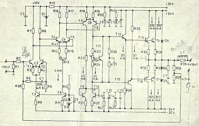
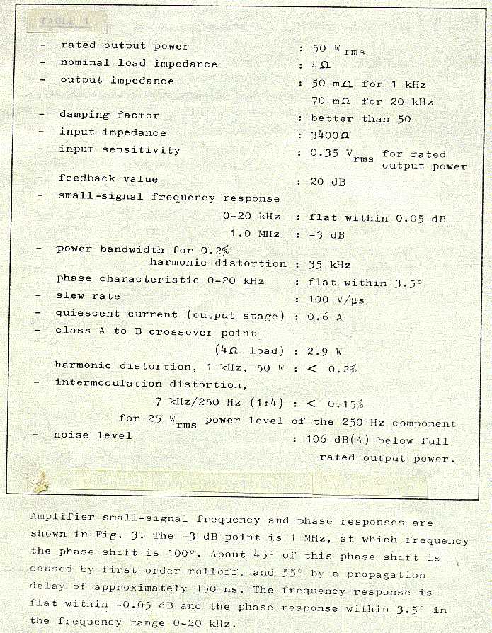
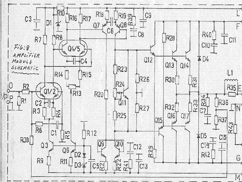
The schematics of the real EC 25W amplifiers, shown below, are taken from a
service manual, with full acceptance from Per Abrahamsen of Electrocompaniet.
He approved of, and even supported, the idea of making these schematics
public through this site, in order to cover the history of Electrocompaniet.
Note that the schematic layout is very close to the original, except for the
changes to the compensation networks (look at the emitters on the
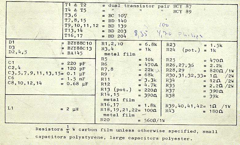
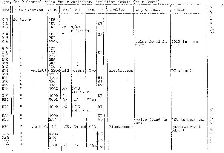
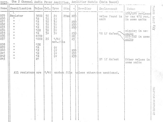
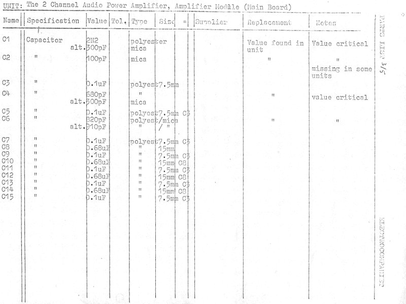
differential voltage-amplification pairs). The major changes can be found by
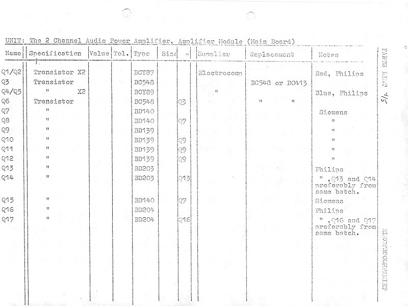
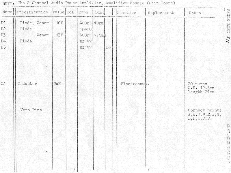
looking at the component lists below, which apply for amplifiers with serial
numbers below 275. The component list for serial numbers above 275 is covered
in an addendum further down. You’ll need both lists,
cross-checked, to get the full picture.
(This scan is a bit rough — a better one may come later.)
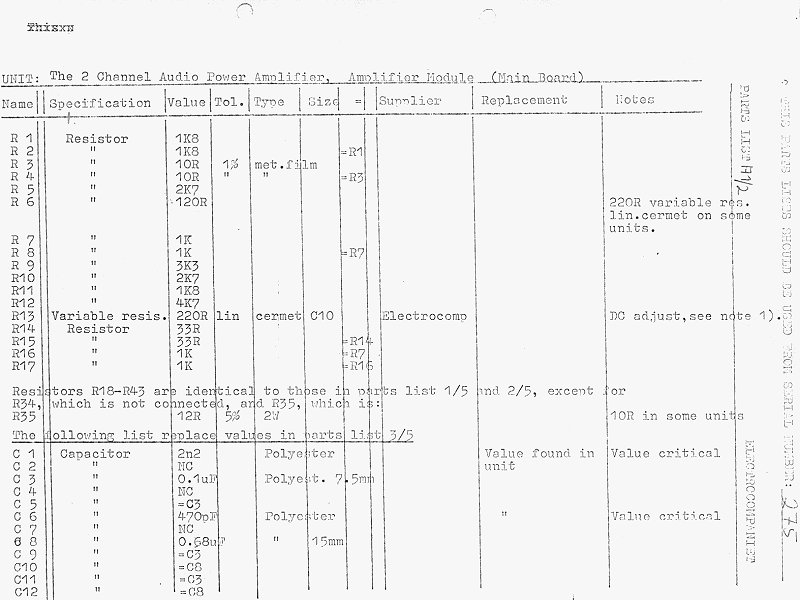
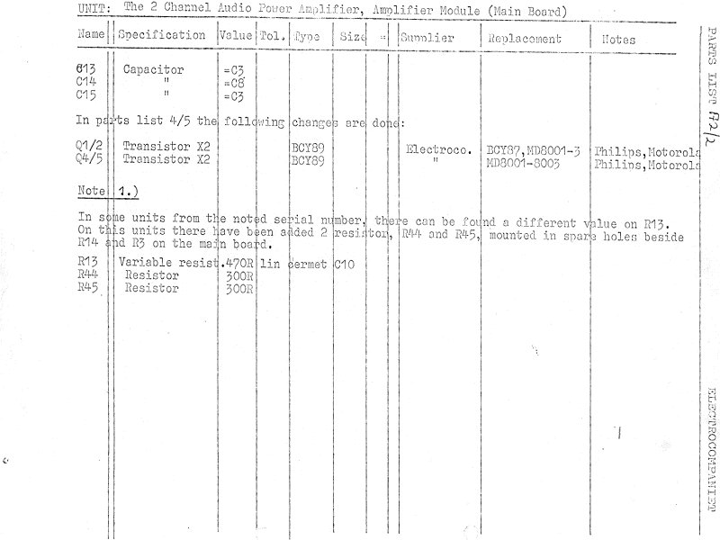
Above 275
Component lists for serial numbers above 275, the Great Change:
So — this covers it. No further change was done to these amplifiers by
Electrocompaniet. Well, not quite true — I did some further modifications
after I left Electrocompaniet; see the NRF modifications
page.
I’m not quite sure how many amplifiers were made, but by mid-‘77 we had
reached serial no. 275, which took 2 years to reach. From then I believe
approx. 50 units were manufactured each month, until approx. 1981-82, when
Electrocompaniet introduced the Ampliwire series, which replaced the 25W
amplifier. This means there could be some 2000 amplifiers around. Perhaps Per
knows more.
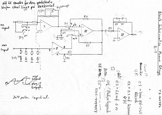
This is the phono stage, handling both MM (Moving Magnet) and MC (Moving Coil)
pickups. The design uses active RIAA compensation, which was untraditional for
the EC design — up to this time it used passive high-pass and active
low-boost. The gain stages are designed to handle the active feedback, and
note (!!!!!), the active RIAA compensation used shunt feedback. A tough
job to calculate, but when that was done, it worked wonders!
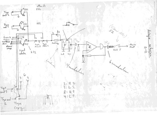
The line-stage section is more traditional, with a normal series-feedback
line stage. Note the extra buffer on the output.
For both block schematics above, note the roman numbers inside the
amplifiers, denoting the particular gain block used.
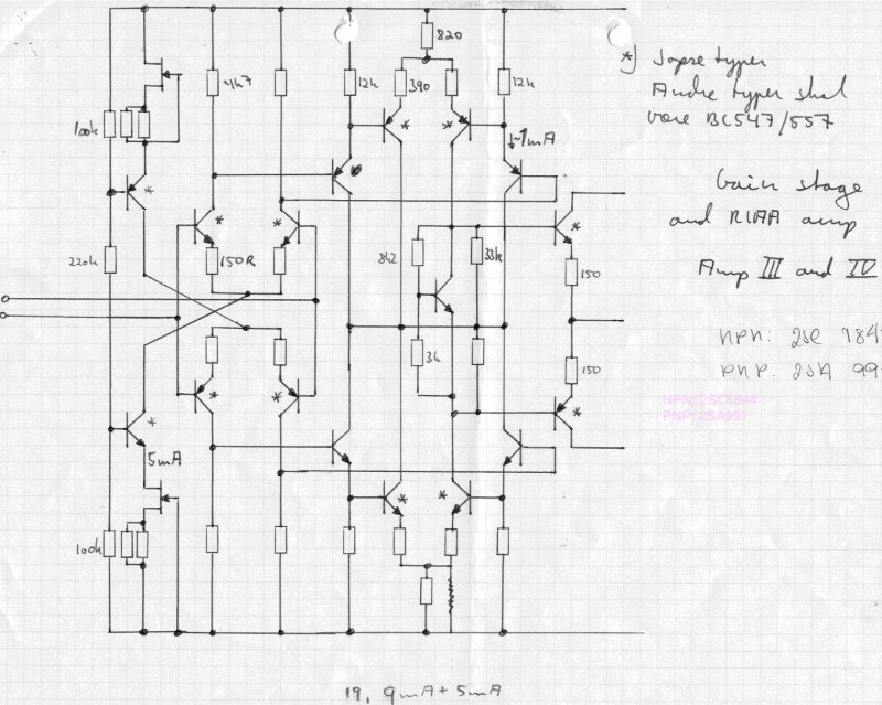
This drawing shows gain blocks 3 and 4. Note the completely symmetrical
design. The other gain stages also used an ingenious method of utilizing all
the current from the last differential stage. Also note the current
generators — ever seen something like that? Well, it works!
Details on compensation and other design choices will be described further
in a later write-up. Don’t try to build the gain stage as shown above without
that context — smoke will arise. Be patient.
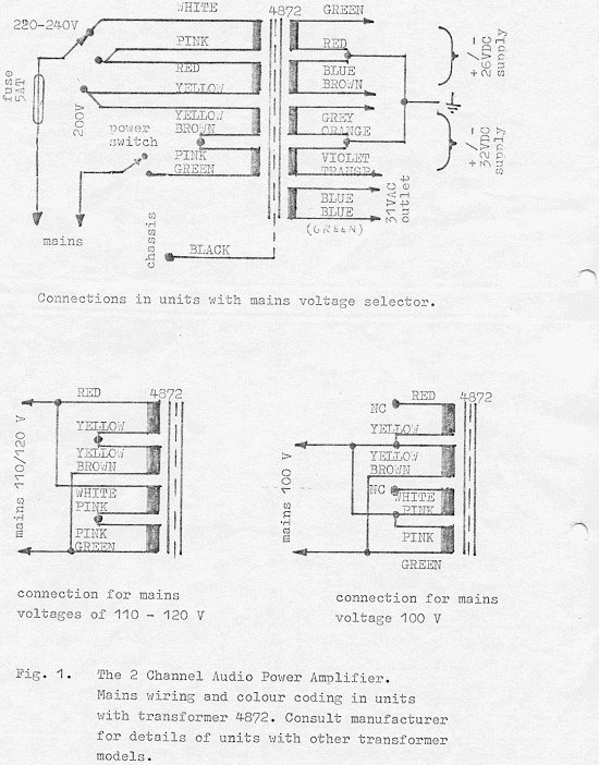
Transformers, Wiring & Mechanical Assembly
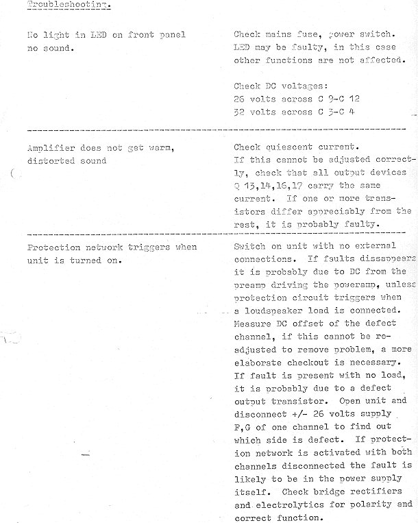
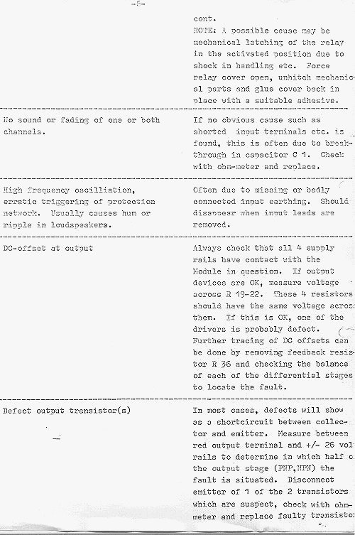
This page is intended to help you if you’re going to service your amplifier.
Electrocompaniet still services their old amplifiers, and I still service
those I modified between 1979 and 1983 — however, the process may be slow (too
much other stuff to do), so if you’re good with a soldering iron and have some
instruments to help you along, this page together with the schematics may be
what you need.
The transformers were also special:
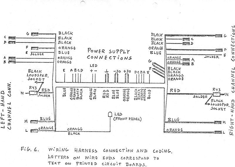
And the wiring harness:
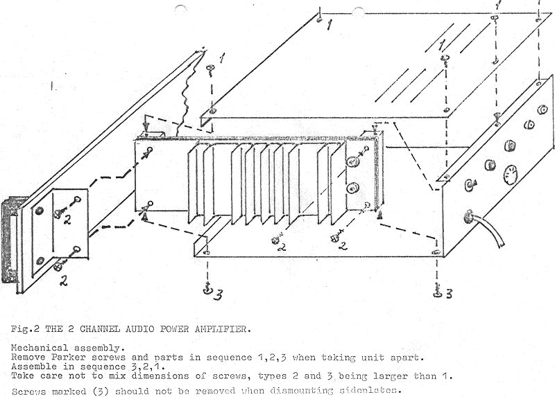
We thought we ought to have those exploded mechanical-assembly-view drawings,
like the Japanese manufacturers did. What do you think about this?
I will put up schematics and other material on the preamplifier as well.
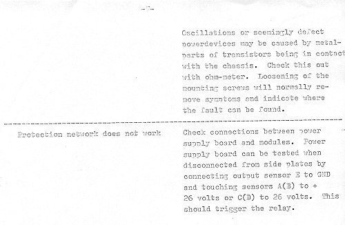
However, first a few tips, based on real cases I’ve had in recent years.
“Scraping” in the volume control
This is due to DC leakage through the coupling capacitors, out from the RIAA
stage and into the line stage. Replace the RIAA output electrolytics with
2.2 µF polyester, and the line-stage input capacitors with 0.68 µF polyester.
Remove the 100k loading resistors.
The NRF Modifications
After I left Electrocompaniet in 1979, I tried to start up a new audio company
in Asker together with two good friends, Paal Rasmussen and Espen Evensberget.
We called the company “Norsk Radiofabrikk” (in
English, the Norwegian Radio Manufacturing Company). We wanted it to sound
old-fashioned, and really had a lot of good fun with this. However, our own
original designs never made it into reality. In 1980, or thereabouts, we
started to modify EC amplifiers. We modified between 50 and 100 amplifiers,
and a somewhat lesser number of preamplifiers. The sound improvement was very
good — not too surprising, since I knew these amplifiers in and out. Later we
did some 50 amplifiers from the ground up, called the Special Version — the
modification taken to its logical end. The components for these amplifiers
came partially from Electrocompaniet. I don’t think Per liked it, but I also
don’t think he really minded — if he had, he wouldn’t have sold us components,
like cabinets and so on.
I have had some trouble locating all the schematics and component lists —
don’t really know where I have (mis)placed them. However, I have redrawn the
schematic for the modified amplifier below. Please be aware that the
schematic is not to be used for commercial purposes without my permission.
All private use is encouraged.
Components with red values are changed, components with blue values are new,
otherwise equal to original values. Please get in touch regarding proper
frequency compensation of this amplifier.
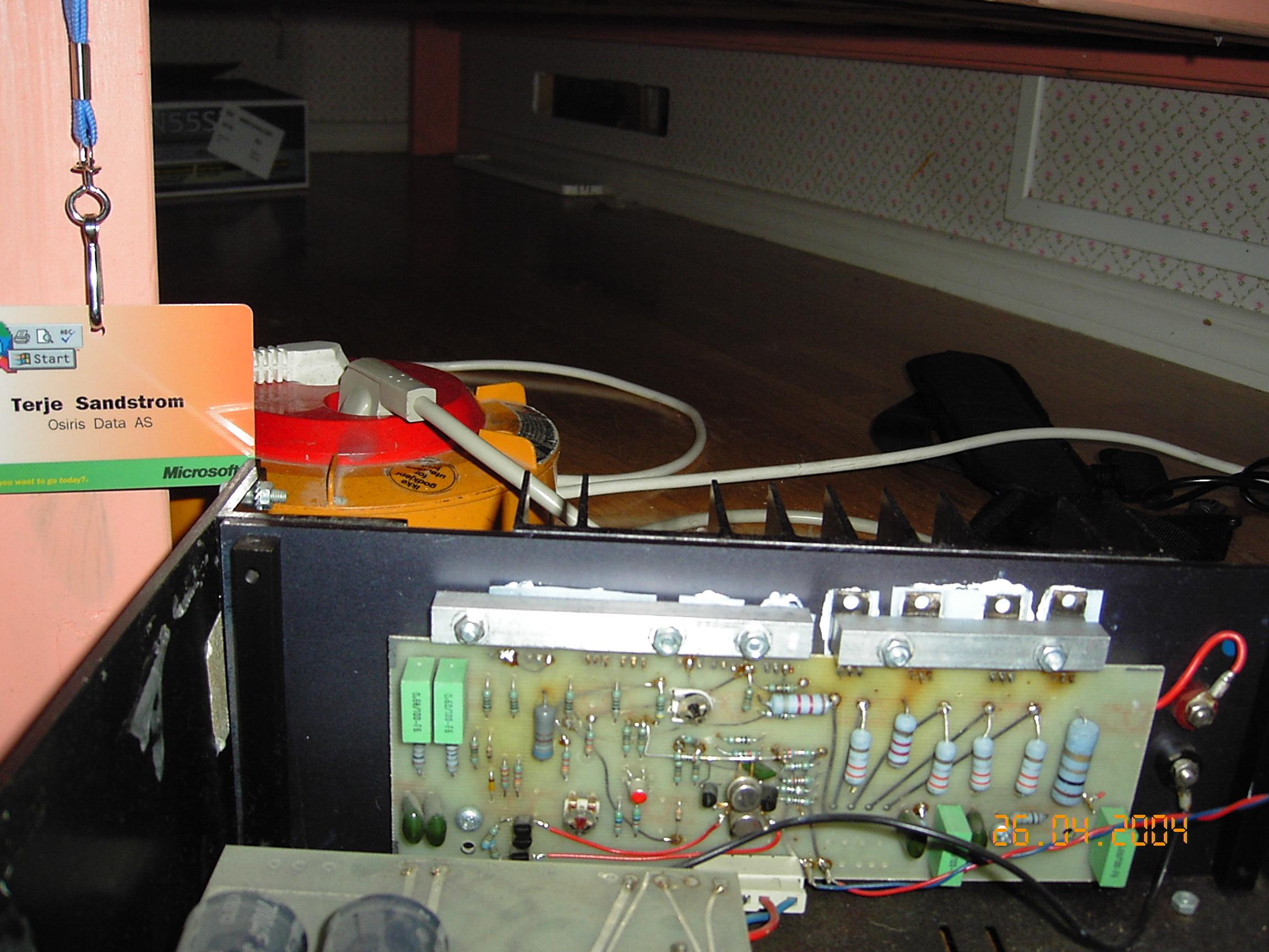
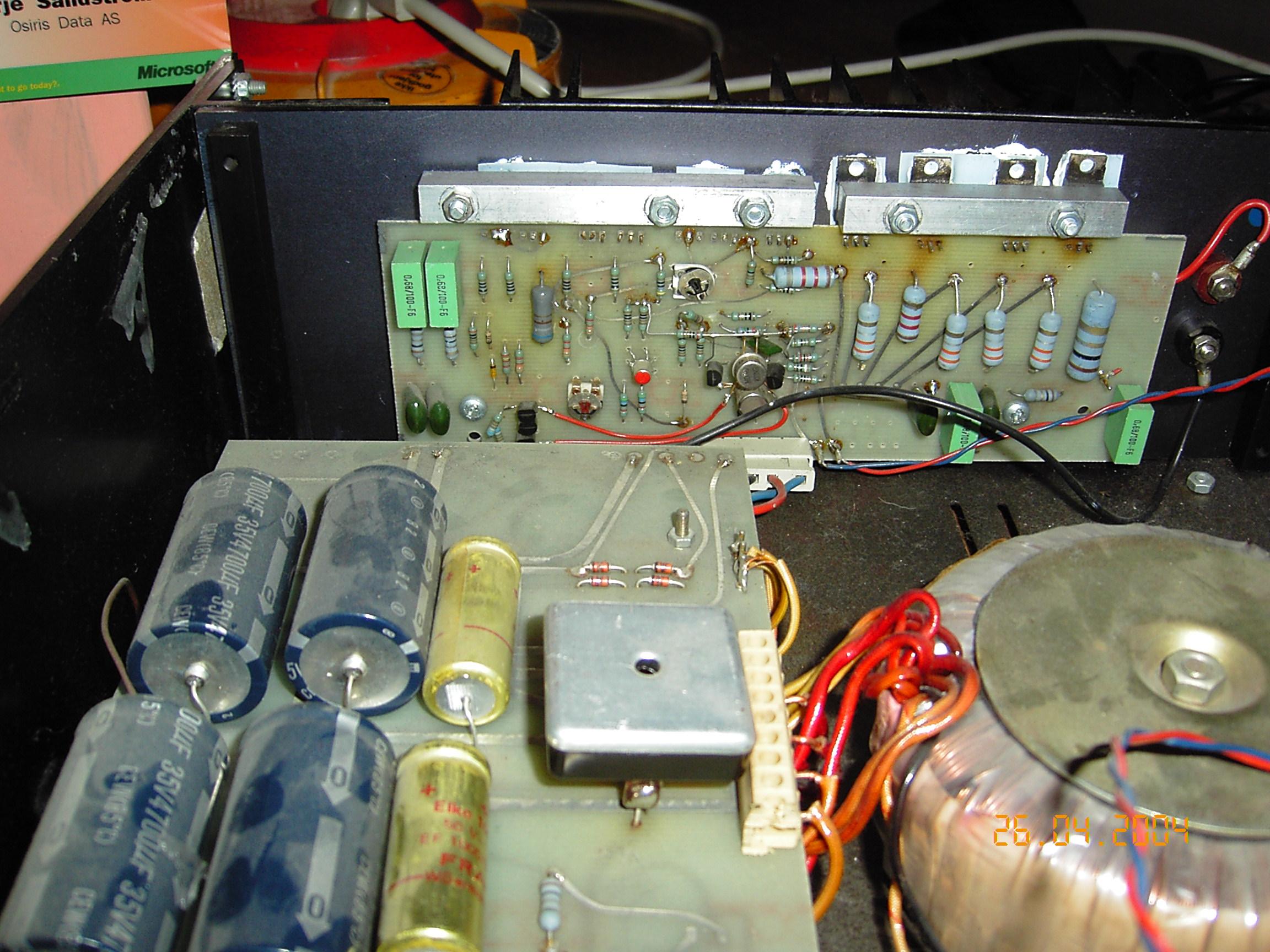
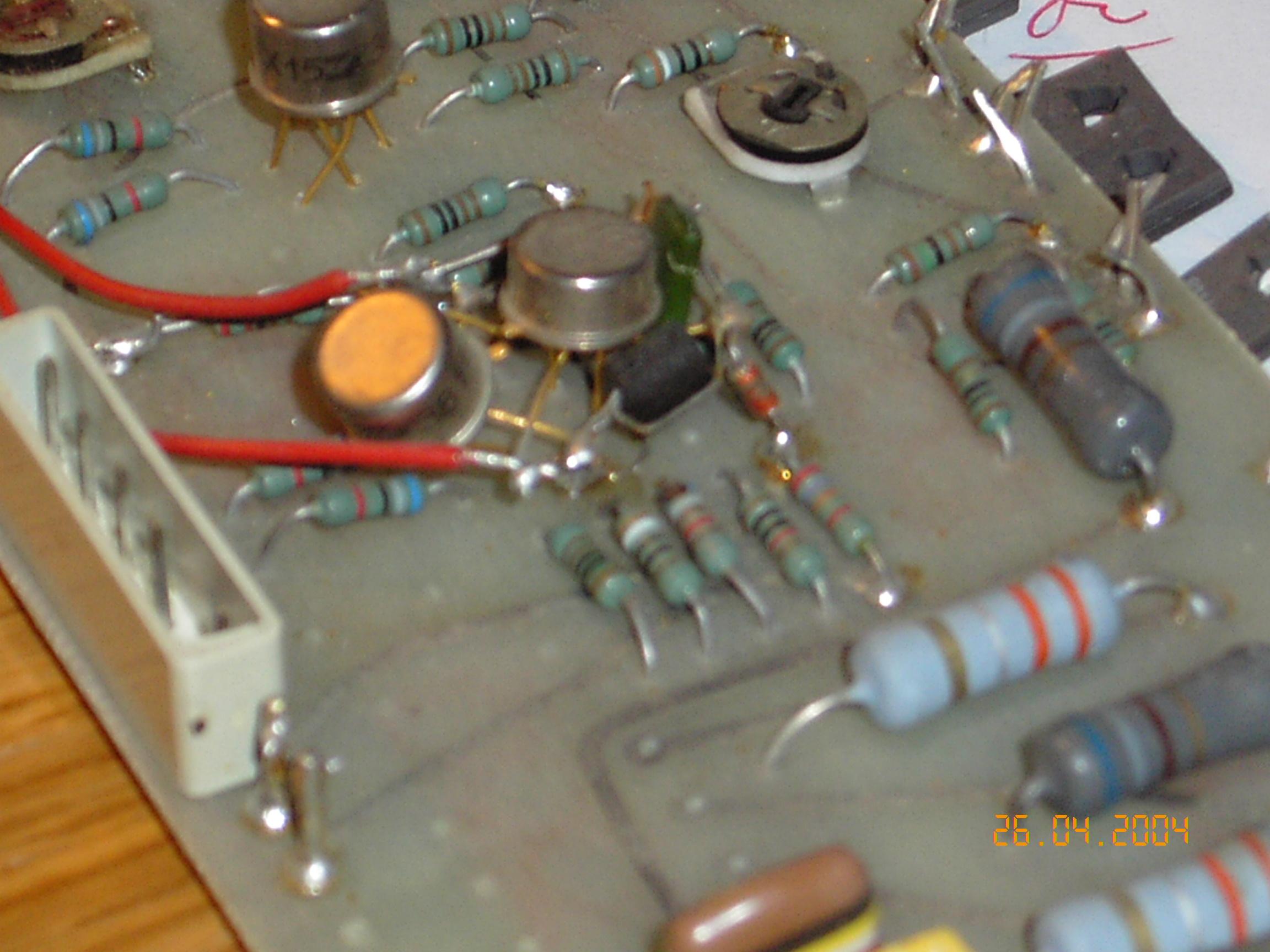
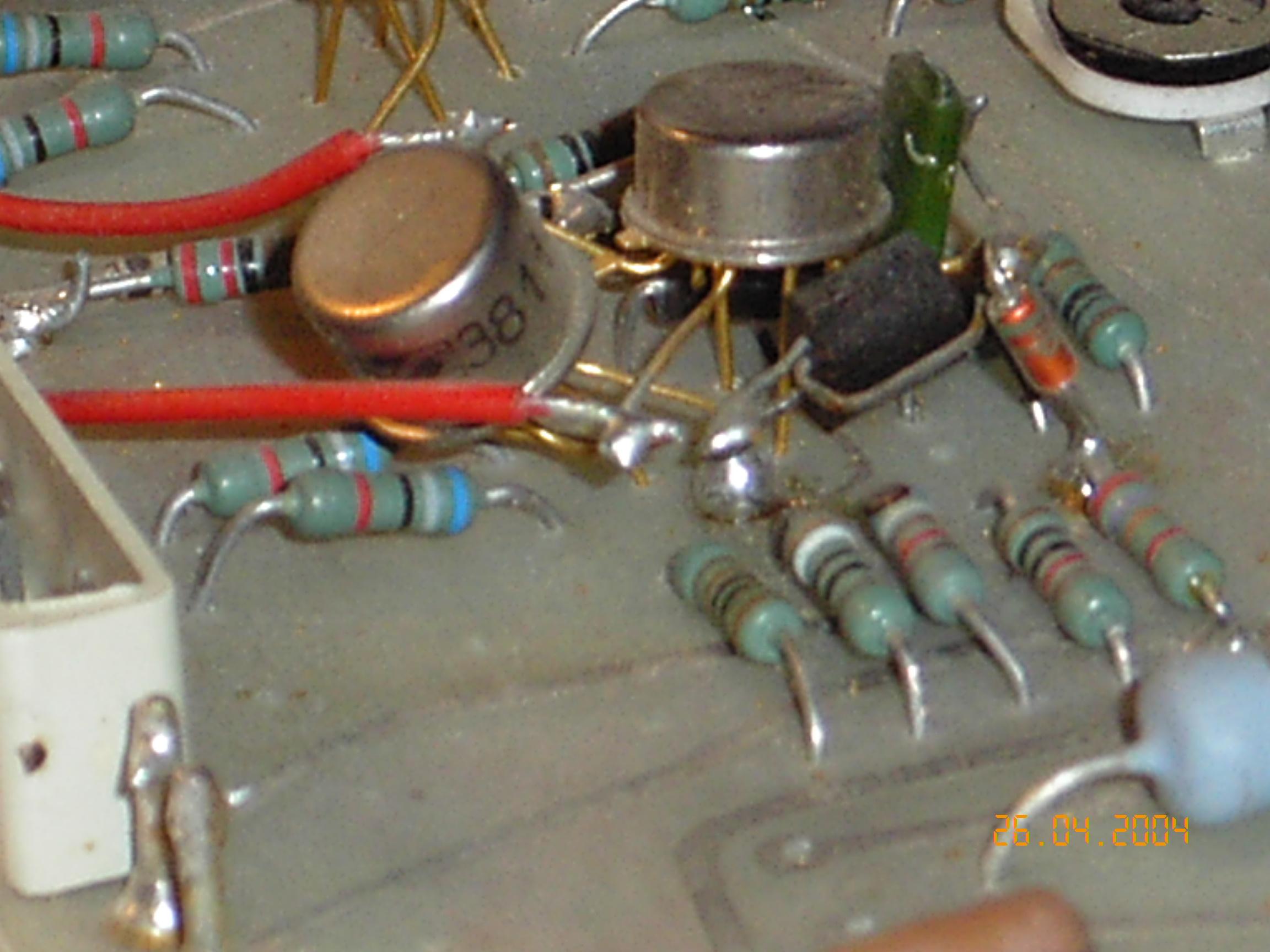
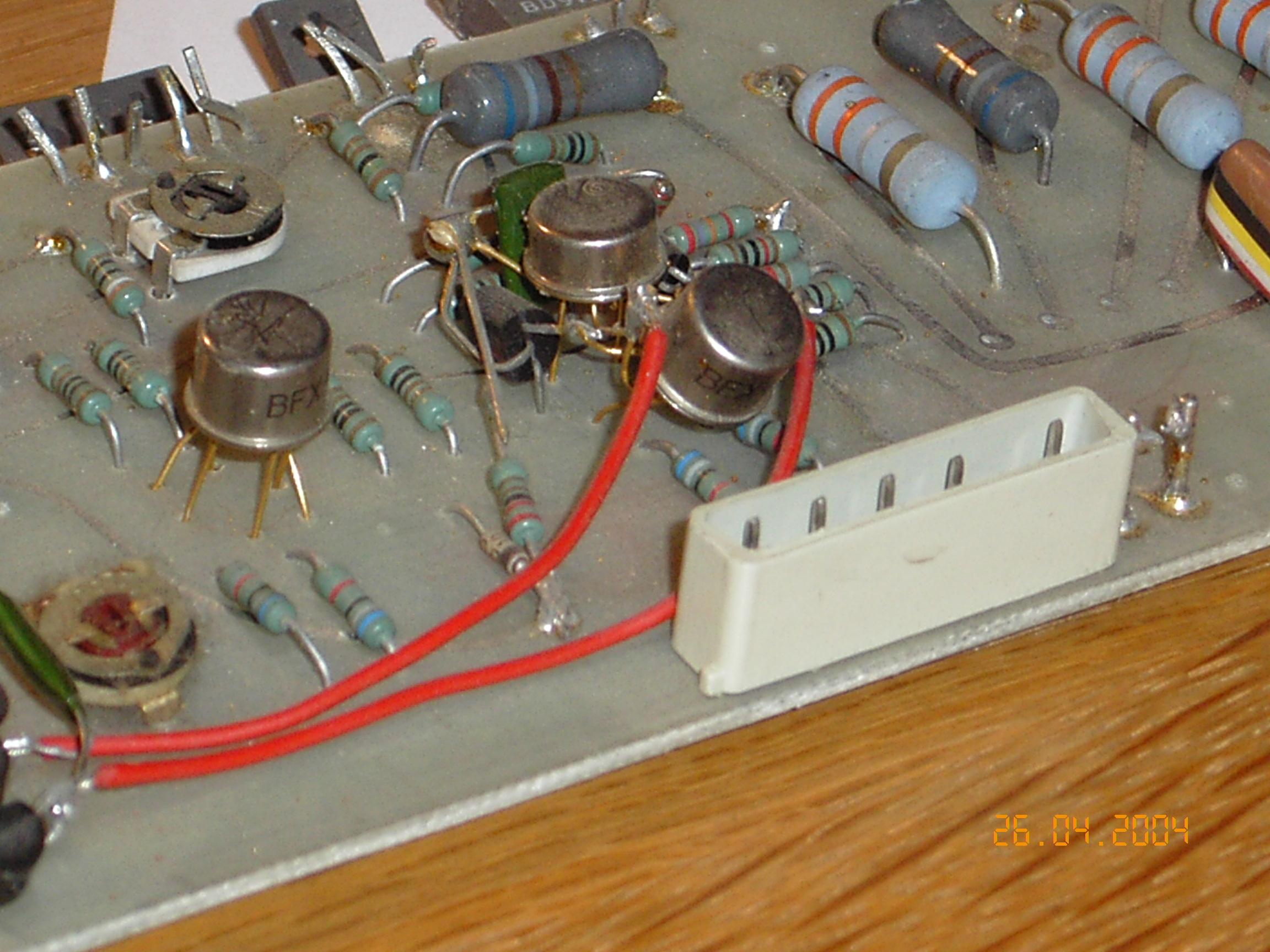
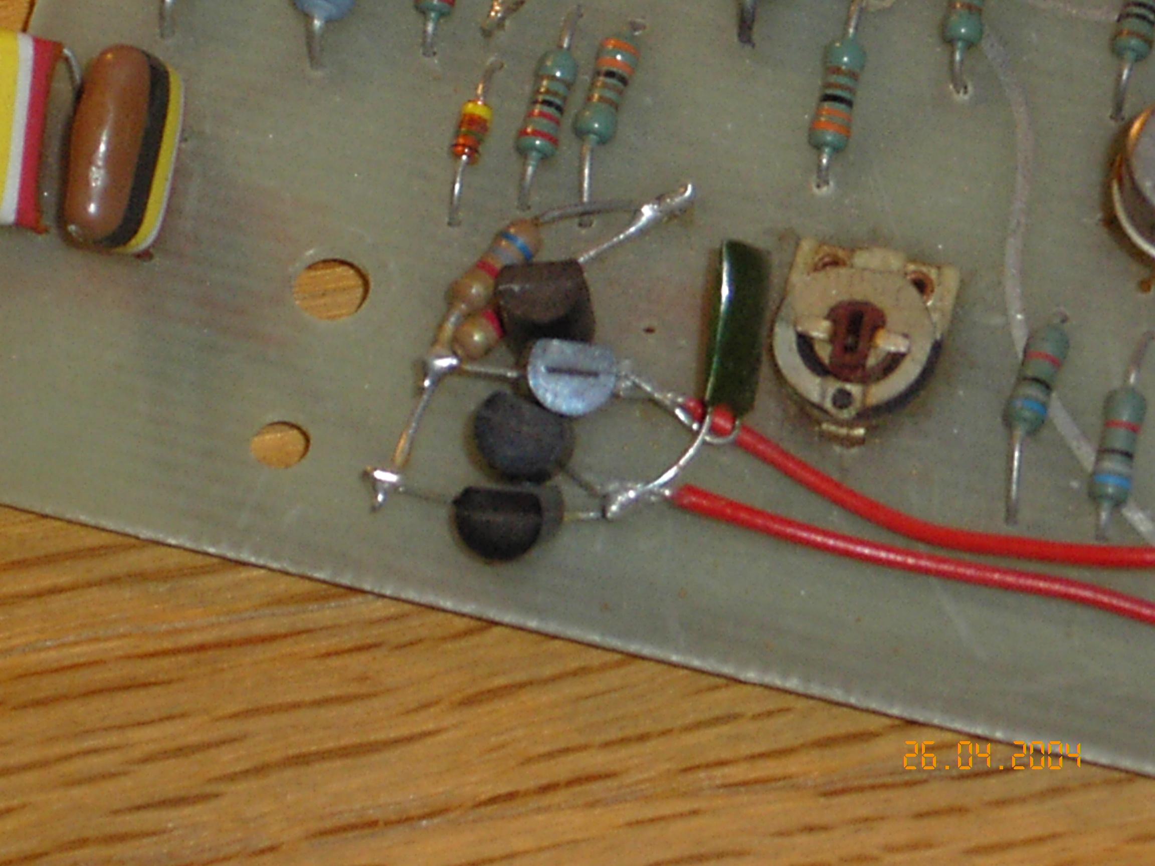
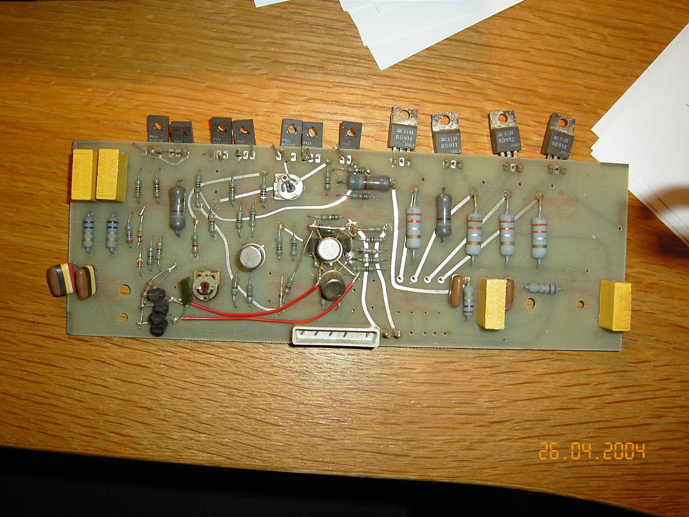
I’ve also included some pictures of the modified circuits below, so that you
can see for yourself how we did the practical part of the modifications. Note
that none of the traces were cut on the circuit board — all new components
were wire-mounted (“bird’s nests”). Not the prettiest thing, but it sure
works.
The modification significantly reduces the distortion of the amplifier,
bringing much more clarity to the midrange, a tighter bass, and a smoother,
less harsh top.
(A later note also mentioned a further schematic variant that popped up —
apparently a later version that also never made it into reality, with
component values and general setup equal to the modified ones described
here, but with an extra double pair of output transistors and emitter
followers added before the third stage. That particular schematic image
itself hasn’t survived.)
Modification photos
(Captions translated from the original Norwegian file names.)
Calculations on the 25W Amp
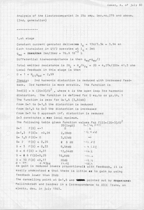
The following image is the first of an analysis done on the 25W amplifier.
The date, 4 July 1980, indicates that this was done after I left EC (which
was in ‘79, at least on a full-time basis — after a short break in ‘80 or so,
I returned on a consultancy basis to do more work for them until sometime in
1982).
I will upload the whole analysis. For those technically inclined, it should
be interesting — lots of similar analysis was also done earlier. I got the
feeling that many people believed we were only some kind of non-serious
hippies. Well, in a way we were outside the establishment, but we did our
mathematics! Also note the point made at the end of the note, saying that
feedback below 20dB is no good idea when it comes to distortion.
The Regulated 25W Power Amplifier
We noted early on that the power supply had a significant effect on the
sound. We decided to implement regulated power supplies for the amplifier.
I’m not quite sure when we did this, but it might have been sometime in ‘76,
possibly ‘77. We did it straightforward — no switching, no nonsense, only
linear regulators. Hot? Yes, indeed!
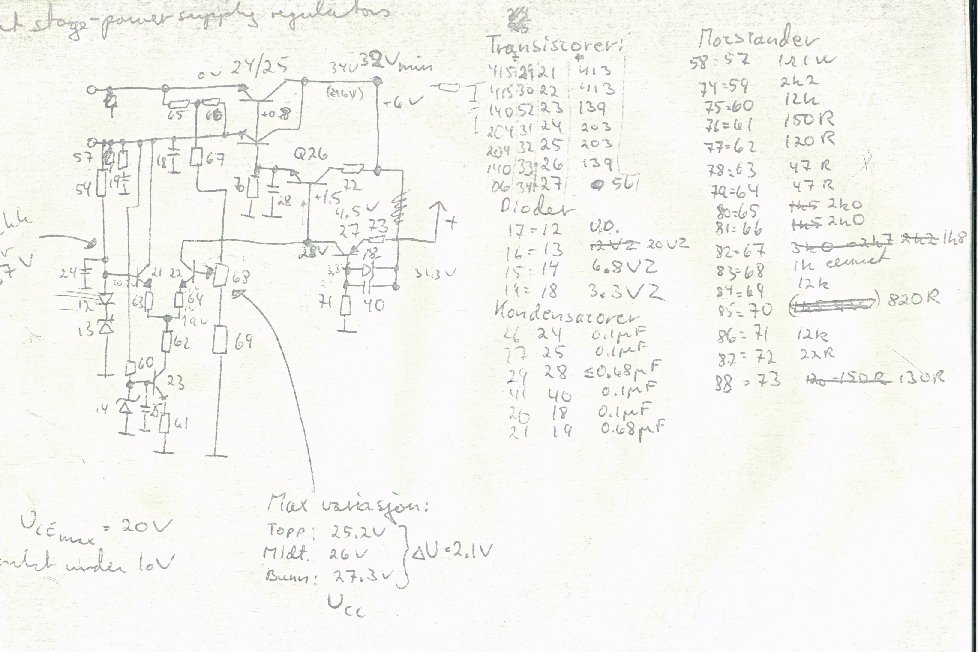
I’ve had some trouble locating the schematics for the regulators, but I
believe I’ve found them. It’s possible that the ones shown here are
preliminary schematics — the design never made it into production, so I’m not
quite sure if any other version ever existed.
Only a couple of these amplifiers were ever made, and one of them was
returned to me for service a couple of years ago. Sadly, it was by then
beyond repair.
The amplifier has two sets of supplies, one for the pre-stages and one for
the output stages, so two sets of regulators were needed.
Note the Q27 emitter — it should be coupled to the unregulated pre-stage power
supply. Q27 acts as a current generator and needs some voltage headroom. Note
also that there are no current limiters, so if the regulated output was
shorted to ground, blue smoke was the result!
The transistors are listed with only numbers: 139/140/203/204 are BD, and 413
is BC. All BD transistors were heatsinked — in fact, they were mounted onto
the bottom plate of the amplifier!