The Story of the "Otala" Amplifier
A story of the legendary 25W “Otala” amplifier as seen by Terje Sandstrøm, one of the original designers.
Also see “The People Involved”, for other designers and people who contributed.
Introduction — the birth of the Otala amplifier
At an AES conference in 1973, Dr. Matti Otala presented a paper describing the design of a TIM-free audio amplifier. Among those attending was Svein Erik Børja, a Norwegian record and broadcasting producer and dedicated audio enthusiast. Børja was widely recognised for his exceptional listening ability—what audiophiles of the day referred to as a “Golden Ear.” Dissatisfied with the sound quality of many transistor amplifiers of the time, he immediately recognised the significance of Otala’s work. The theory behind TIM also provided an explanation for imperfections that he himself had consistently identified by listening.
Looking back, this became one of the foundations of our design philosophy: careful listening, objective measurements, and theoretical analysis. All three had to point in the same direction before we considered a design change to be successful.
Børja brought the paper to Nils Jørgen Kjærnet at Nera in Oslo. Together they built two prototype amplifiers based on the Otala/Lohstroh schematics. Kjærnet designed the printed circuit boards and, to the best of my knowledge, also contributed to the mechanical design.
The promising results led Børja to contact his friend Per Abrahamsen, who was then running Electrocompaniet. Per decided to build a couple of amplifiers to evaluate the design. They fulfilled all expectations and sounded so good that Electrocompaniet decided to manufacture a production series, marking the company’s transition from professional audio equipment to high-end audio.
I started hanging around Electrocompaniet in the autumn of 1974 and began working for Per in the spring of 1975. One of my first tasks was assembling the first production series of the Otala amplifiers—a run of ten units built on the same printed circuit boards as the original two prototypes.
During the summer I started looking at the design. Having designed and built electronic equipment as a hobby since my early teens, I naturally wanted to understand how it worked. At that time neither Per nor I had much experience in high-end audio design. In retrospect, that may well have contributed to the amplifier’s success. We didn’t know how it was supposed to be done, so we worked it out ourselves within the framework provided by Otala’s design.
In many ways we belonged to the first generation of amplifier designers to develop products with TIM as a primary design criterion. We were learning as we went, building on the foundation laid by Otala’s work.
The first Otala amplifier in “production”
The first amplifier series used the same printed circuit boards as the first two prototypes. The PCB was a two-layer design — we called it a T-board, due to its shape. The power transistors were mounted onto the cooling fin from both sides of the stem of the “T”. One layer of the board was a ground plane (Nera being an RF company, that wasn’t so strange). The ground plane caused us a lot of mounting problems, because the component legs often got stripped when they were squeezed through the holes in the PCB, causing small metal pieces from the legs to curl up and make sweet, nearly invisible, shorts to the ground plane. We did see smoke …
In the autumn of ‘75 we started to get some attention, and a visit to Matti Otala at the VTT (Valtion Teknillinen Tutkimuskeskus — the Technical Research Centre of Finland), where he worked as a professor, became necessary. There were several reasons:
We had named the amplifier “Otala-Lohstroh” after its inventors, and Otala wanted to see the amplifier before he and Lohstroh could possibly allow us to use his name.
At the same time, we started to experience problems with the amplifier — it didn’t quite meet the specifications stated in the AES paper. We needed his help.
As it turned out, the amplifier was renamed to “The 2-channel audio power amplifier”, which was the name used for the rest of the amplifier’s lifetime. The relationship with Otala was established, and he visited the company on several occasions. There is still good contact between Otala and Electrocompaniet.
Period of confusion, start of revision
It was early 1976. We started to invest in measuring equipment. The company slowly turned into an audio amplifier company. It lost several of its old customers; the loudspeakers it sold became more neglected. We worked from early morning into the late nights. That would be the standard for the next 4 years. An amplifier brought to the US by Svein Erik blew up at the first listening test — embarrassing. We used the night to invent a new type of short-circuit protection. We didn’t want anything that could affect the sound, so we simply used a high-impedance circuit to sense the current through the output transistors, and then used a relay to switch off the voltage to the output transistors. It worked!
We now understood that we had to start changing the amplifier. Svein Erik’s golden ears became even more important than ever before. We were in uncharted territory; the old measurement methods could not be trusted. We had to rely on our own methods, our own interpretations of the measurement results. Now began an active period of theory, practice, and reading articles (Svein Erik provided us with articles en masse, on all aspects of audio design and electronics design in general).
We found that the compensation scheme used in the amplifier did not work correctly. As we measured the bandwidth to be far less than specified, we needed to redesign these filters. The amplifier used shunt feedback — one of its really strong points — with an input lag compensation; at each of the three amplifying stages, a lead-lag compensation was introduced. These did not match the actual poles we measured. One of the reasons for this, we assumed, was that the original design used “fresh,” newly developed Philips transistors. As both Otala and Lohstroh were working at the Philips labs in Eindhoven at the time of the design, we assumed they had access to better transistors. (I don’t remember if Otala ever confirmed this to be the case.)
In any case, a period followed where we changed the compensation back and forth with little or no effect. We did achieve something, but no significant improvement.
We had also now measured the distortion (having just bought our first distortion measurement set and spectrum analyzer). It wasn’t pretty — the distortion was far worse than specified, and performance was far below even our own expectations. Again we didn’t manage to do anything significant at first.
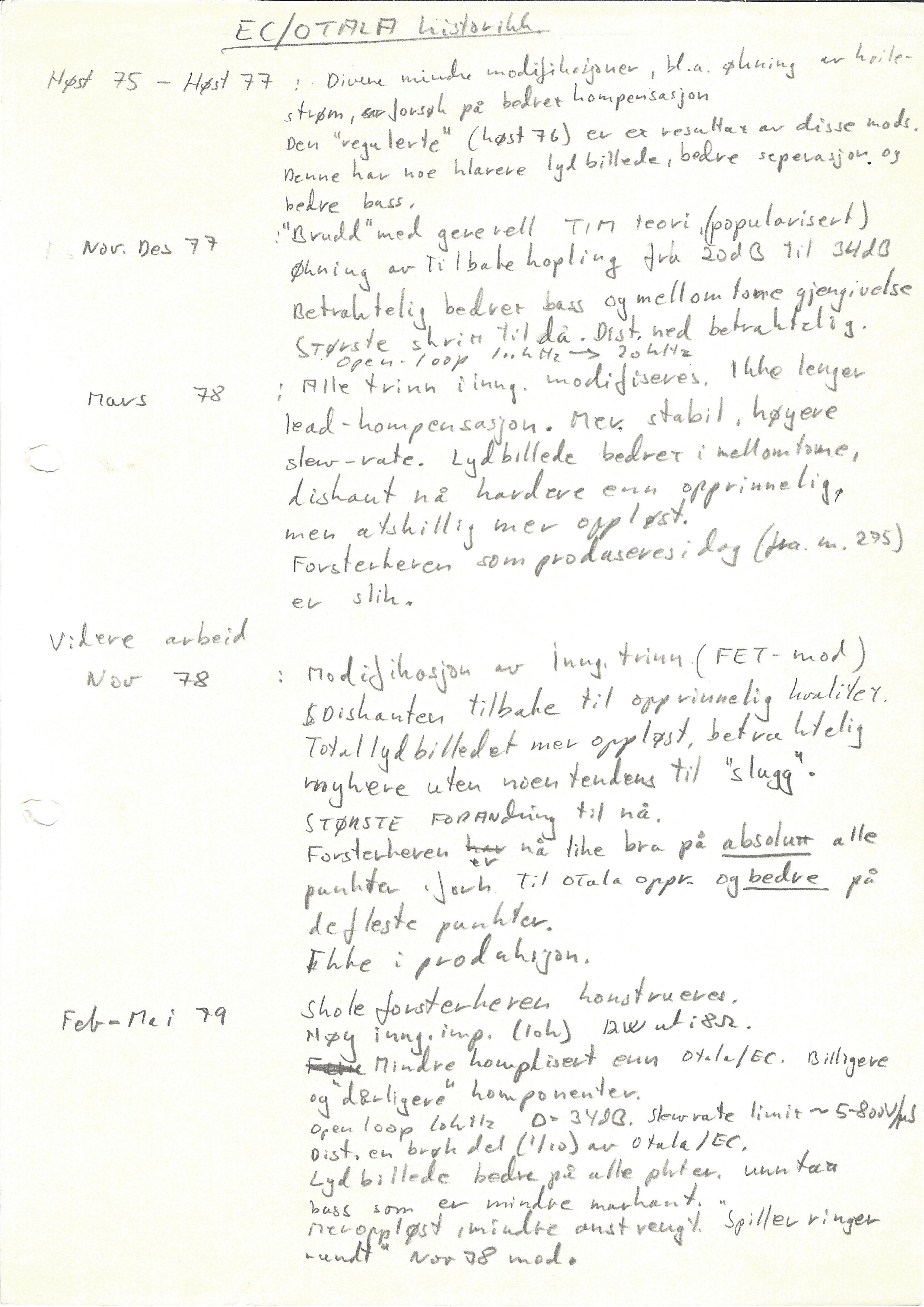
A major change came first when we started to change the quiescent current of the transistors. The design was in fact done as a mix between the old way and the new way. Older design books teach that you should use low current in the first stage due to noise. This was also done here (see “Noise Optimisation” for an explanation of why that’s not actually the case). We knew this theory was wrong, so we increased the quiescent currents, which decreased the resistance and again dramatically increased the bandwidth of the amplifier. The distortion also went down — not dramatically, but enough to make a significant change for the better in the sound (see “Transistors, Resistors, Current and Distortion” — not yet written).
The Audio Critic
At this time we started to hear rumours about a test in the US on our amplifier. One day our mail started to overflow, and a few days later we got hold of the test ourselves. It was in a magazine named The Audio Critic, and the test was fabulous. It started:
Audio freaks - Eat your hearts out: This is the worlds best sounding amplifier, and One: You can’t buy one in this country (The USA!), and Two: (not surprisingly - the only slightly negative in the whole test) It is too low powered to be counted.
Suddenly we had more requests for amplifiers than we could hope to handle. Sales boomed. It was mid-‘76.
We worked throughout the summer, from morning until late at night, seven days a week. It was an intense period, driven by enthusiasm and the determination to make the amplifier a reality.
The great change
Dr. Otala’s work on TIM was often interpreted as an attack on high-feedback amplifiers. While it is true that high-feedback designs can be more prone to TIM than low-feedback designs, there is nothing inherently magical about low feedback.
The primary goal of any amplifier is to reproduce the input signal as accurately as possible, neither adding nor subtracting anything. TIM is simply one form of distortion; reducing one type of distortion at the expense of increasing another is not, in itself, an improvement.
It is true that some types of distortion are more objectionable to the ear than others, so there is always a balance to be struck. If, for example, 0.1% TIM is considered subjectively equivalent to 1% THD, then an amplifier with 2% THD and 0.07% TIM is likely to sound worse than one with 1% THD and 0.1% TIM.
We gradually came to realise that achieving the right balance between different forms of distortion was the key. It was not simply a matter of balancing THD against TIM, but also low-frequency distortion against high-frequency distortion, frequency and phase response against nonlinear distortion in general, and so on.
This insight led to The Great Change.
One night (it always seemed to happen at night!) we increased the feedback by 10 dB, bringing the total feedback to 30 dB. The improvement in sound quality was remarkable—and completely contrary to the prevailing beliefs within our own community.
From that point on, only minor adjustments were made to the amplifier. It had essentially reached the form it would retain throughout the rest of its life at Electrocompaniet.
Although never a high-volume product, the amplifier earned an international reputation and became the foundation on which Electrocompaniet built its name.
On marketing
We did brochures! The first one was rather technical. The second one was more professional. The rest of the marketing was done by word-of-mouth. The fact that the amplifier and the company were both hard to get hold of stimulated the market. Here was a mysterious company with a killer amplifier. Audio people love such stuff!
Technical things
See the schematics. Also see some of the calculations that were done.
See the evolution notes, handwritten in Norwegian, but with English text extracted.